
Our Solar Installation Workflow: From First Enquiry to Commissioning
Author: Steve Fairless
Published: 27th March 2026 · Updated: 2nd September 2026
A professional solar installation is a design, approvals and commissioning process — not simply a day spent fixing panels to a roof. The quality of the finished system depends on the information gathered before installation, how the electrical and structural design is developed, whether the network route is correct, how safely the work is programmed and how thoroughly the system is tested and handed over.
At Sustainable Energy Engineering, we manage the job as one connected workflow. The customer should understand what we are proposing, the roof and electrical system should be suitable for the design, the expected generation should be explained before contract, and the completed installation should be documented well enough to operate and maintain for years.
Below is the process we use to move from an initial enquiry to an installed and commissioned solar PV system. The exact route varies with the property: a straightforward domestic tiled roof is different from a commercial three-phase project, a battery retrofit or a site requiring G99 approval.
Updated: 2nd September 2026.
How Does a Solar Installation Work?
- Enquiry and energy information: we establish the property, electricity use and what the customer wants the system to achieve.
- Initial design: we assess likely roof capacity, generation, self-consumption and equipment options.
- Survey: we confirm roof, structure, access, shading, cable routes and electrical conditions.
- Final engineering: module layout, inverter, strings, battery, protection and mounting are confirmed.
- Approvals: DNO and planning requirements are resolved as applicable.
- Scheduling: equipment, scaffold, safety and installation dates are coordinated.
- Installation and testing: the mechanical and electrical system is built and commissioned.
- Handover: the customer receives documentation, monitoring access and operating guidance.
Stage 1: We Start With What You Want the System to Do
Two homes with identical roofs can need different systems. One customer may want the strongest financial return from solar alone; another is preparing for an EV; another wants battery backup; another has a heat pump and high winter electricity demand.
We therefore start with annual electricity use, recent bills and, where possible, half-hourly smart-meter data. We ask about future loads and tariff plans. We also establish whether there is existing solar, battery storage or an EV charger that must be integrated rather than treated as a separate system.
Useful Information at Enquiry Stage
- property address and roof type;
- annual electricity consumption and tariff;
- half-hourly data where available;
- photographs of roof, meter and consumer unit;
- details of existing PV, battery or EV equipment;
- planned EV, heat pump, electric hot water or extension;
- whether backup power is required;
- any known roof repairs, planning constraints or building works.
Stage 2: Initial Solar Design and Performance Estimate
Before a customer commits, the proposal should explain more than the number of panels. MCS MIS 3002 Issue 6.0 sets out the performance-estimation and handover requirements for MCS solar PV systems. The estimate includes installed PV capacity, roof orientation and inclination, postcode region, a shade factor and expected annual output; where storage is included, it also records estimated self-consumption and grid independence.
That is the foundation we want. We show what the proposed array is expected to generate and how the assumptions relate to the property. If battery storage is included, we separate estimated solar self-consumption from the storage effect rather than adding a vague percentage saving.
Four Numbers We Keep Separate
| Number | What it tells us |
|---|---|
| PV array capacity (kWp) | The DC nameplate size of the installed modules. |
| Estimated annual generation (kWh) | The modelled energy output after orientation, inclination and shade assumptions. |
| Self-consumption (kWh / %) | The estimated solar energy used on site rather than exported. |
| Grid independence / self-sufficiency (%) | The estimated share of total electricity demand met by local solar and, where included, storage. |
Stage 3: Survey the Roof, Structure and Access
The survey turns an initial concept into a buildable design. We confirm dimensions, roof covering, pitch, orientation, shading, roof condition, mounting zones, rooflights, chimneys, access, drainage and the route between array and electrical equipment.
For homeowners considering solar PV for the home, this is also where we identify work that should happen before the installation. A damaged roof covering, uncertain structural area or problematic cable route is cheaper to resolve in design than after scaffold and equipment arrive.
MCS MIS 3002 Issue 6.0 includes roof suitability, mounting, weather-tightness and structural requirements within its scope. We use those requirements as part of the design discipline rather than treating the roof as simply a platform for modules.
Stage 4: Survey the Electrical Installation
We assess the incoming supply, meter arrangement, consumer unit or distribution board, earthing, spare ways, cable routes and suitable positions for the inverter, battery, isolators and monitoring equipment. Existing generation and chargers matter because their capacity can affect the complete network picture.
This is also where we decide whether additional electrical work is needed. A solar quotation that ignores the actual distribution board or proposed battery location can look cheaper on paper but leave important work unresolved.
Stage 5: Finalise Module Layout, Strings and Inverter Design
Once survey information is confirmed, we finalise the module layout and electrical configuration. We check string voltage across expected temperature conditions, inverter MPPT operating windows, module and inverter current limits, roof orientations and any shading or mismatch that affects string grouping.
Panel wattage alone does not determine inverter design. An east-west array can have a different simultaneous power profile from a single south-facing array of the same kWp. A battery or backup requirement can also change inverter selection.
The Final Layout Should Be Electrically Valid and Maintainable
We do not force the last module into a poor roof position simply to increase the headline kWp. The array needs sensible edge zones, access, string design and serviceability as well as strong generation.
Stage 6: Confirm DNO Connection Requirements
The distribution network operator needs to know about connected generation through the appropriate process. The March 2025 Distributed Generation Connection Guide explains the G98 and G99 routes. G98 covers compliant microgeneration with combined registered capacity up to and including 16 A per phase; systems above that route use G99.
We establish the connection requirement before the installation. On larger systems, the DNO may specify export or protection conditions. Where storage is present, aggregate generator capacity can matter, so we do not assess the PV inverter in isolation.
Stage 7: Check Planning and Property Constraints
Many domestic roof-mounted solar installations in England can be carried out under permitted-development rights, subject to conditions and exceptions. The Planning Portal guidance was updated following changes that took effect in August 2026, so older assumptions should not simply be copied into a new project.
Listed buildings, conservation constraints, unusual siting and commercial properties can need additional consideration. We want planning questions resolved before the customer has scaffold in place.
Stage 8: Procurement, Scaffold and Installation Planning
Once the design and approvals are ready, we coordinate equipment, scaffold or access systems, installation labour and electrical work. Product availability can change, so any substitution must remain electrically, structurally and commercially suitable rather than being treated as a like-for-like swap based only on wattage.
Roof safety is fundamental. HSE states that all roof work is highly dangerous and must be planned, and that roofs should be treated as fragile until a competent person confirms otherwise. We build safe access and edge or fragile-surface controls into the work package.
Stage 9: Mechanical Installation
The roof team installs the mounting system and modules to the approved design and product instructions. Weather-tightness and fixing quality matter just as much as module alignment. Cables are supported and protected so they do not lie against abrasive surfaces, sag into gutters or create future maintenance problems.
Photographs of key details can be useful for future service because the completed modules hide much of the mounting system. Good records make later roof or PV work easier to plan.
Stage 10: Electrical Installation
DC strings are wired and routed to the inverter or appropriate DC equipment, and the AC connection is completed through the designed protective devices. Batteries, CTs or meters, export limitation and EV-related controls are integrated where specified.
Labelling, isolation and safe access need to make sense to the next competent person who works on the property. We do not see the electrical finish as hidden work that stops mattering once the enclosure door is closed.
Stage 11: Commissioning and Testing
Commissioning confirms that the installed system matches the design and operates safely. Tests and checks depend on the equipment and installation, but include the PV strings, polarity, insulation, protection, inverter settings, grid parameters, monitoring and any battery or export-control functions.
A system that has produced power once is not automatically a properly commissioned system. We want the controls, alarms and energy metering to be working so that the customer can tell what the installation is doing after we leave.
Stage 12: Handover and Customer Explanation
MCS MIS 3002 includes commissioning and handover requirements because documentation is part of the installation. The customer needs to know how to isolate the system, what normal operation looks like, what monitoring shows, which warnings matter and who to contact if a fault occurs.
We provide the applicable equipment information and handover records for the installed system. For batteries or smart controls, we also explain the operating mode and any reserve or tariff settings that affect day-to-day behaviour.
What Happens After Installation?
Monitoring makes it possible to compare real performance with the expected pattern and to spot obvious faults. It should not be used to judge a system from one cloudy day, but a sustained change in output, inverter alarm or missing string should be investigated.
Our solar servicing and maintenance supports systems after commissioning, including fault diagnosis, inverter issues and work where an existing array needs to be altered or recommissioned.
Why We Keep the Workflow Connected
Problems often arise at the interfaces: a roof layout that does not suit the strings, an inverter that does not suit the battery, a cable route that was never surveyed, or an array that reaches installation before DNO conditions are clear. One connected workflow reduces those handover gaps.
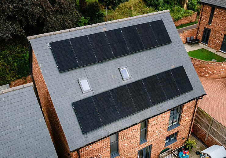
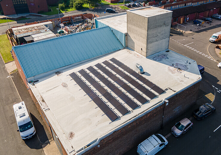
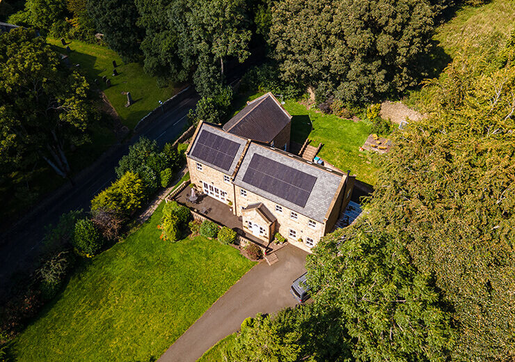
Our solar case studies show completed projects in the context of real properties rather than isolated product specifications.
Our View: A Good Installation Is Decided Before the First Panel Is Lifted
Installation workmanship is essential, but the installer can only build a good system if the design, survey and approvals are sound. We want the day on site to be the execution of a resolved plan, not the point at which basic decisions are made for the first time.
Planning a Solar, Battery or Integrated Energy Project?
Send us your electricity usage, property details and any future EV or heat-pump plans. We can take the project through design, survey, connection requirements, installation and commissioning as one engineering process.