
How to Install Solar Panels in the UK
Author: Steve Fairless
Originally Published: 24th December 2023 · Updated: 3rd September 2026
A professional solar installation is a controlled engineering process: we assess the building and electricity use, design the array and electrical system, obtain the required approvals, install the mounting and cabling safely, test every circuit, commission the inverter and provide a complete handover pack. The panels are the most visible part, but their long-term performance depends just as much on the roof survey, string design, inverter selection, cable routes, protective devices, network connection and quality of the final testing.
At Sustainable Energy Engineering, we do not treat installation day as the beginning of the job. Most of the decisions that protect output, weather-tightness and serviceability are made before equipment reaches the property. The physical installation then follows a design that has already been checked against the roof, the electrical supply and the way the customer uses energy.
This guide explains what happens at each stage, what a homeowner should expect to see in a professional proposal and why rooftop and electrical work should be carried out by competent people rather than approached as a general DIY project.
How Are Solar Panels Installed? The Short Answer
- We survey before we specify. Roof condition, structure, orientation, shading, access and electrical capacity all affect the design.
- We model energy, not just panel count. The proposal should show expected annual generation and how much may be used, stored or exported.
- We establish permissions and the network route. Planning, building, leasehold and DNO requirements are checked before work proceeds.
- We install a certified mounting system. Fixings must transfer loads into the structure while preserving the roof covering and drainage.
- We build and protect the electrical system. String voltage, current, polarity, isolation, earthing, surge protection and cable routes are designed together.
- We test, commission and document. A finished array is not complete until the electrical results, inverter settings, monitoring and handover information have been checked.
1. Start With the Property and the Energy Requirement
The first question is not “how many panels fit?” It is “what should this system achieve?” We ask for annual electricity consumption and, where available, half-hourly data. We also ask about planned EV charging, heat pumps, electric hot water, home working, extensions or commercial equipment because these can materially change the right array and storage size.
For a home, our solar PV design process balances roof capacity with the value of the electricity generated. A larger array can be sensible where future demand is rising or export has value, but maximum panel count is not automatically the best financial or electrical answer.
What We Need Before We Design
Those units describe different things. Confusing stored energy, generated energy and instantaneous power is one of the quickest ways to mis-size a system.
2. Complete a Roof, Site and Access Survey
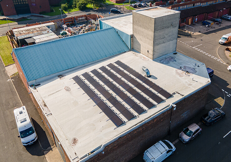
We inspect the proposed mounting surface, not just its compass direction. On a pitched roof this includes the covering, battens or decking, rafters or trusses, flashings, valleys, ridges, verges, existing repairs and any signs of water ingress. On a flat or commercial roof we also consider membrane condition, drainage, structural loading, fire zones, access routes and whether ballast or penetrative fixings are appropriate.
Shade is recorded from chimneys, dormers, trees, parapets and neighbouring buildings. A photograph taken at one time of day cannot show the full annual pattern, so the design needs to consider the changing height and direction of the sun. Safe access and scaffold requirements are also planned at this stage. Roof work remains high-risk construction activity, and HSE guidance states that almost one in five construction deaths involves roof work.
A Sound Array Cannot Compensate for a Failing Roof
If we identify active leaks, widespread broken coverings, weak structural members or a roof likely to need major renewal soon, we would rather resolve that before installation. Panels can be removed later, but coordinating roof work first usually avoids duplicate scaffold, labour and recommissioning costs.
3. Design the Module Layout and Predict Performance
We map the usable roof area with required setbacks, access, obstructions and mounting zones. Each roof plane is modelled according to its orientation, pitch and shading. The result should be a credible annual generation estimate rather than a generic output figure copied from another property.
The current MCS solar standard requires a performance estimate and information about factors that can affect it. We also distinguish between generation and savings. Two households with the same array can achieve different bill reductions because one uses more energy during daylight, has a battery or receives a different export rate.
| Design question | Why it matters | What we document |
|---|---|---|
| Where can modules be fitted? | Determines safe, maintainable DC capacity. | Roof plan, module dimensions, setbacks and obstruction zones. |
| How should modules be grouped? | Orientation and shade affect string and MPPT behaviour. | String schedule, tracker allocation and electrical limits. |
| What will the array generate? | Supports an informed financial decision. | Annual kWh estimate and material loss assumptions. |
| How will energy be used? | Self-consumption, storage and export have different values. | Consumption assumptions, battery strategy and export position. |
| Can the building and supply accept it? | Protects structure and electrical/network compliance. | Structural evidence, supply details and approval route. |
4. Select Compatible Modules, Inverter and Battery Equipment
The module and inverter are checked as an electrical pair. We calculate string open-circuit voltage at low temperature, operating voltage through expected conditions, current per input, short-circuit current, permitted DC oversizing and the number of modules each MPPT can control. Similar panel wattages do not guarantee compatibility.
Where storage is included, our solar and battery design also considers usable capacity, charge and discharge power, backup requirements, operating temperature, location, metering and whether the chosen architecture is AC- or DC-coupled. We avoid selecting a battery only because its headline kWh figure looks attractive.
5. Confirm Planning, Building and DNO Requirements
Many domestic roof-mounted systems can be permitted development, but that is not a blanket exemption. Listed buildings, conservation considerations, flats, leasehold restrictions, unusual siting and local conditions can change the position. We check the correct route rather than assuming every roof is identical.
The grid connection is a separate issue. Systems within the G98 route are limited by registered capacity to 16 A per phase; on a nominal 230 V single-phase supply that corresponds to 3.68 kW. Larger or aggregated generation can require the G99 process, and export limitation may need to be engineered and agreed. The DC array size, inverter registered capacity and export limit are related but not interchangeable.
3.68 kW Is a Connection Threshold, Not a Universal Panel Limit
A property can have a DC array larger than 3.68 kWp and, where properly designed and approved, an inverter system above 3.68 kW. We assess the complete generation and storage arrangement rather than forcing every project into one familiar number.
6. Plan Safe Access, Deliveries and Isolation
Before installation begins, scaffold or another suitable access method is arranged, delivery routes are confirmed and fragile surfaces are identified. The work area must protect occupants, neighbours and installers. Modules are large, wind-sensitive objects; handling them on a roof requires planning, not improvisation.
Electrical isolation is equally important. PV modules generate DC whenever exposed to light, so “turning the inverter off” does not make every rooftop conductor dead. The installation sequence, connectors, cable management and test procedures must be designed around that reality.
7. Install the Roof Mounting System
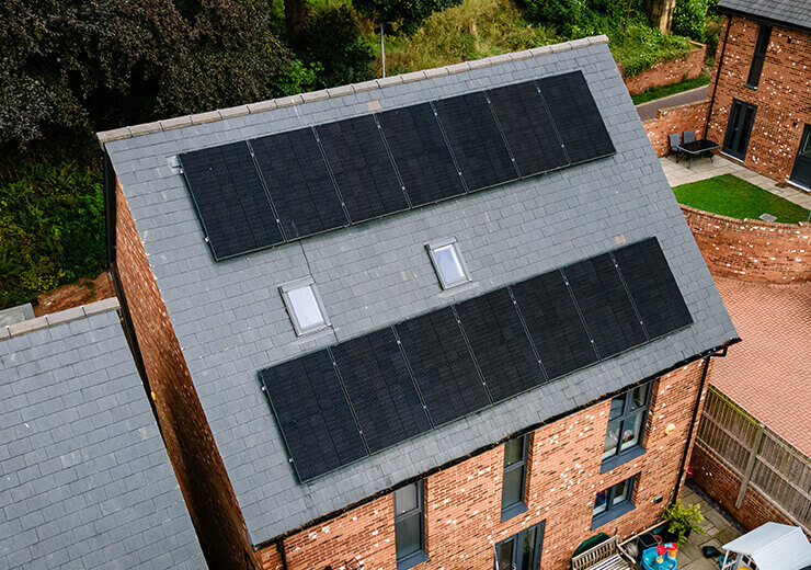
On a typical tiled or slate roof, coverings are carefully lifted so brackets can be fixed to suitable structural members. The bracket and flashing detail must suit the exact roof covering. Tiles or slates should not be crushed or left carrying loads they were never designed to support. Any damaged covering is replaced, and roof gaps are not enlarged simply to make a bracket fit.
Rails are aligned, fixed and checked before modules are clamped. The fixing density and layout account for wind actions, roof zones, module dimensions and mounting-system instructions. On flat roofs, the design may use ballast, mechanically fixed frames or a combination, but membrane protection, drainage and structural capacity remain essential.
8. Install DC Cabling, Inverter and AC Equipment
Modules are connected into the designed strings using compatible connectors and correctly supported solar cable. Cables should not rest on roof coverings or sit in standing water, and connector pairs should not be treated as universally interchangeable because they look similar. Polarity is checked before connection to the inverter.
The inverter and any battery equipment are installed in locations that meet manufacturer and electrical requirements for access, ventilation, temperature and fire safety. AC protection, isolation, metering, earthing and surge protection are completed to the design. Cable routes are labelled and arranged so future servicing does not require guesswork.
9. Test and Commission the System
Commissioning verifies that the built system matches the design. It includes visual inspection, continuity and polarity checks, insulation-resistance testing, string measurements, protective-device checks, inverter configuration and confirmation that the system responds correctly to the grid connection. The exact test schedule depends on the installation, but it should never be reduced to “the app shows power”.
Monitoring is then configured so the customer can see generation and, where metering supports it, consumption, battery flow, import and export. We also explain what normal seasonal variation looks like and what warning signs justify a service call. Our solar servicing team relies on good commissioning records because they provide the baseline for future diagnosis.
What We Expect in a Complete Handover Pack
- system description, layout and electrical schematic;
- module, inverter, mounting and battery datasheets;
- string details and commissioning test results;
- planning, building and network records relevant to the project;
- warranties, operating instructions and shutdown information;
- monitoring access and explanation of alarms;
- maintenance guidance and installer contact details;
- MCS certificate and associated documentation where applicable.
10. Judge the Installation by the Finished System, Not the Number of Panels Fitted
A well-installed system should be structurally secure, weather-tight, electrically compliant, clearly documented and easy to monitor. It should also be based on realistic energy assumptions. A fast installation is not a successful installation if the design has ignored shade, the inverter is mismatched, the roof detail is poor or the customer cannot obtain the records needed later.
We aim to leave customers with a system they understand and that another competent engineer could inspect years later. That means recording what was fitted, why it was chosen and how it was tested.
Planning a Solar Installation?
Tell us about the property, your annual electricity use and any plans for batteries, EV charging or future electrification. We will assess the roof and electrical requirements before recommending a system.