
How Are Solar Panels Installed?
Author: Steve Fairless
Originally Published: 11th December 2023 · Updated: 3rd September 2026
How Are Solar Panels Installed? The Short Answer
A professional installation normally moves through survey, structural and roof checks, system design, planning and network checks, safe roof access, mounting, DC wiring, inverter and optional battery installation, AC connection, electrical testing, commissioning, DNO notification or approval, certification and customer handover. The exact sequence can vary by property, but each stage protects safety, performance and long-term reliability.
- We survey and design before anything is fixed to the roof. Roof condition, structure, shading, cable routes, electricity use and network requirements all affect the final system.
- Roof safety is part of the installation design. HSE says almost one in five deaths in construction work involve roof work, so access and fall protection cannot be treated as optional extras.
- MCS requires the roof to remain structurally sound and weather-tight. Domestic modules should normally stay at least 400 mm from roof edges unless specific measures are taken.
- Planning and DNO requirements are checked before the install where needed. A qualifying G98 route differs from a G99 or export-limited application.
- The electrical installation is tested and commissioned before handover. Inverter settings, protection, monitoring and documentation all form part of the completed system.
- We hand over a documented installation, not just working panels. The customer should understand the equipment, monitoring, warranties, isolation and future service route.
The Installation Process at a Glance
| Project phase | Main work | What the customer should have at the end of it |
|---|---|---|
| Survey and design | Energy use, roof, shading, structure, cable routes, equipment and performance modelling. | A system layout and specification that fits the property rather than a generic panel count. |
| Planning and network | Permitted-development checks, DNO route, inverter/export strategy and any pre-connection application. | A design that is compatible with the property and network route. |
| Roof installation | Safe access, structural fixings, rails, weather-tight detailing, module mounting and DC cable management. | A mechanically secure array that protects the roof and follows the mounting instructions. |
| Electrical integration | Inverter, battery where specified, AC connection, protection, earthing, isolation and labelling. | A complete electrical system ready for formal testing and commissioning. |
| Commissioning and handover | Electrical tests, inverter/battery settings, monitoring, DNO/MCS records and customer documentation. | A tested system with certificates, warranties, operating guidance and a support route. |
Stage 1: understand the property and electricity demand
Before we specify equipment, we need to understand what the customer is trying to achieve. Annual electricity consumption, daytime demand, future EV or heat-pump plans, battery objectives and export preferences all influence the design. A system built only around the maximum roof area can be financially and technically different from one designed around the property's load profile.
For a domestic solar PV system for a home project, the initial information usually includes recent electricity usage, roof type, orientation, access, shading and the proposed inverter/battery location. Commercial projects can require half-hourly consumption data and more detailed electrical information.
Stage 2: carry out the site and roof survey
The survey checks roof condition, structure, dimensions, usable areas, obstructions, shading, cable routes and the existing electrical installation. The current MCS MIS 3002 standard requires the roof structure to be assessed for suitability and unusual structures or areas of doubt can require a suitably qualified structural engineer.
Weather-tightness matters just as much as load. Mounting should not create an avoidable leak path, and the roof warranty position should be considered before work starts. MCS also requires installers to consult the roof warranty provider where applicable and tell the customer in writing if the proposed work may invalidate that warranty.
Stage 3: design the array and estimate performance
The survey information is turned into a proposed module layout, inverter specification and annual-generation estimate. MCS requires written technical information including the module and inverter datasheets, proposed module layout and a performance estimate. Where relevant, optimiser, microinverter or battery datasheets are also part of the pre-contract information.
Layout design considers more than fitting a target number of modules. Roof edges, ridges, gutters, shading, wind exposure and access all influence the final arrangement. For domestic roofs, MIS 3002 includes a 400 mm roof-edge consideration unless specific measures justify another design.
Stage 4: planning and DNO checks happen before the physical install where needed
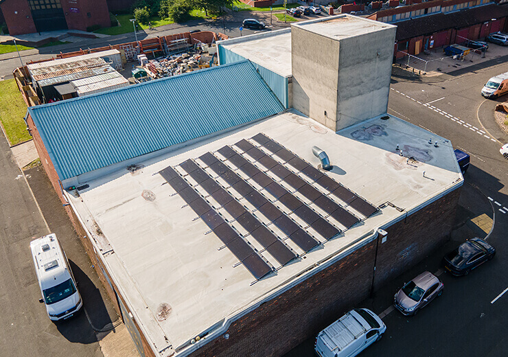
Many ordinary domestic roof arrays in England are permitted development, but listed buildings, conservation restrictions, flat roofs and other circumstances can need additional planning attention. Separately, the electricity network connection route depends on the generating equipment.
Current ENA G98 covers micro-generators up to and including 16 A per phase. On a nominal 230 V single-phase supply, that corresponds to 3.68 kW of registered generation capacity. Systems outside the G98 conditions normally follow G99 or another applicable connection route, which can require approval before installation.
We treat the network route as a design input rather than an afterthought. A customer asking for a larger inverter or battery system may need a different DNO application, export limitation or equipment configuration.
2026 Rules That Materially Change a Real Installation
| Current reference | Published requirement or figure | What it changes on site |
|---|---|---|
| MCS roof edge | Modules should not be within 400 mm of a domestic roof edge unless specific measures are taken. | We do not maximise panel count by ignoring edge-zone wind uplift, ridge security, drainage or snow-shedding considerations. |
| MCS roof condition | Roof structure must be checked by a suitably competent person; unusual structures or doubt require a qualified structural engineer. | The mounting design starts with the roof that actually exists, not an assumed standard construction. |
| MCS roof warranty | The roof-warranty provider should be consulted where a warranty exists, and the customer must be told in writing if the installation may invalidate it. | Roof warranty risk is resolved before the array is fixed in place. |
| England planning | Rules updated 27 August 2026 with a transition to 27 August 2027; pitched-roof panels remain limited to 200 mm projection and flat-roof equipment to 600 mm above the roof. | We check the current planning route rather than assuming every roof-mounted system follows the same conditions. |
| G98 notification | Qualifying connect-and-notify installations are notified within 28 days. | Network paperwork is part of commissioning rather than an optional administrative extra. |
Stage 5: safe access and scaffolding are prepared
Roof work is one of the highest-risk parts of the project. HSE states that all roof work is highly dangerous and that almost one in five deaths in construction involve roof work. Safe access, edge protection, fragile surfaces and competent workers therefore have to be planned before modules are carried onto the roof.
On typical sloping domestic roofs, scaffolding and suitable edge protection are used to control fall risk. Fragile roofs need additional precautions. These controls are not cosmetic extras; they are part of completing the installation safely.
Solar panels should not be treated as a DIY roof job
The electrical side involves potentially dangerous DC voltages and the roof work itself is high risk. Professional installation combines work-at-height controls with electrical competence, structural assessment and grid compliance.
Stage 6: install the roof anchors and mounting rails
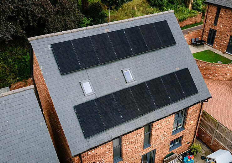
On a typical tiled or slate pitched roof, the installer identifies structural fixing points, lifts or removes the necessary roof covering and fixes mounting hardware to the structural members. Rails are then aligned and secured. The roof covering is reinstated around the brackets in a way that maintains weather resistance.
MCS specifically addresses tile and slate interfaces: roof coverings may need appropriate notching or flashing so that mounting hardware does not create pressure points or prevent correct seating. The exact method depends on the roof covering and mounting system.
Stage 7: mount and electrically connect the PV modules
The modules are lifted into position, aligned and clamped to the mounting system in accordance with the product instructions. DC cables are routed and secured to avoid abrasion, unsupported loops, sharp edges and exposure that could cause premature deterioration.
Modules may be wired in strings to a central or hybrid inverter, or connected to panel-level electronics such as microinverters or optimisers where the chosen architecture uses them. Polarity, connectors and cable management are critical because faults on the DC side can be difficult to interrupt once the array is generating.
Stage 8: install the inverter and, if specified, battery storage
The inverter converts DC electricity from the array into AC electricity suitable for the property and grid. It needs a location that meets the manufacturer's environmental, access and ventilation requirements. Cable length, route and serviceability also matter.
Where a solar battery is included, its installation is a separate engineering task. Battery siting, fire safety, electrical protection, communications and operating temperatures must be considered. The battery should not simply be placed wherever spare wall space happens to exist.
Stage 9: connect the AC side to the property
A competent electrician connects the inverter output into the property's electrical installation using appropriate protective devices and isolation. The design must coordinate with the consumer unit, earthing arrangement and existing protective measures. Labelling and isolators allow future engineers or emergency personnel to identify the PV circuits.
If upgrades are needed to the consumer unit, earthing or supply arrangement, those should be identified early so they do not become a surprise during commissioning.
Stage 10: test and commission the complete system
Before handover, the installation is tested to confirm that the DC and AC circuits are safe and correctly configured. Depending on the system, tests and checks can include polarity, insulation resistance, protective devices, inverter settings, generation, communications and monitoring.
The engineer then commissions the inverter and any battery, verifies that monitoring is reporting correctly and confirms that the system behaves as designed. A successful app login is not a substitute for electrical testing.
Stage 11: complete the DNO registration or approval process
For a straightforward single-premises G98 installation, the “connect and notify” route can allow installation first, followed by notification to the DNO within 28 days. The GOV.UK energy-device registration guidance and DNO procedures set out this requirement. Larger or more complex G99 systems generally require the relevant application/approval route before connection.
The paperwork should match what has actually been installed: inverter model, registered capacity, export-limitation equipment where applicable and commissioning information. This is one reason changing equipment at the last minute without checking the network application can cause problems.
Stage 12: MCS certification and customer handover
The customer should receive the documentation needed to understand and operate the system. That can include system layout, component information, warranties, electrical certificates, MCS certificate, DNO information, monitoring instructions and shutdown/isolation guidance.
We also explain what normal generation looks like, how to spot faults and when to contact us. A good handover turns a completed installation into a system the owner can actually manage.
How long does installation take?
The physical roof and electrical work on a straightforward domestic system can be relatively quick, but the overall project duration can be much longer because design, scaffold scheduling, equipment availability, DNO approval and any planning or structural work occur around the installation days. A G99 application or network upgrade can be the critical path on a larger project.
That is why a professional quotation should distinguish the expected installation duration from the total project programme.
What makes one solar installation better than another?
| Installation area | What good practice looks like |
|---|---|
| Survey | Real roof dimensions, shading, structure and electrical condition checked. |
| Design | Layout and performance estimate match the actual property. |
| Roof work | Correct structural fixings and weather-tight detailing. |
| Electrical work | Protected, labelled and tested DC/AC circuits with suitable equipment. |
| Network | Correct G98/G99 route and accurate installed-capacity information. |
| Handover | Certificates, warranties, monitoring and operating guidance supplied. |
Component quality matters, but installation quality determines whether those components operate in the conditions they were designed for. Roof integrity, cable management, inverter location, protection settings and documentation all affect long-term performance.
What happens after installation?
Solar is low-maintenance but it should still be monitored. Unexpected generation drops, inverter warnings, physical damage or electrical faults need investigation. Our solar servicing work covers inspections, diagnostics and remedial support for both systems we installed and suitable systems installed by others.
Customers who are still at the planning stage can request a solar quote. We start with energy usage and property information so the proposal reflects the system that can be installed safely and the output it is reasonably expected to produce.
The installation process in one sentence
Solar panels are installed by surveying and designing the system first, creating safe roof access, fixing a weather-tight mounting system, installing and wiring the modules, integrating the inverter/battery and AC protection, testing the system, completing the correct network and certification paperwork, and handing over a documented installation to the customer.
Planning a Solar Installation?
We can assess the roof, electricity demand, network route and equipment together so the proposed system is buildable, compliant and straightforward to hand over.
Request a tailored quote from Sustainable Energy Engineering.